- Advantages
- Products
- Applications
- Support
- Design
- Download
- Certification
- News
- Contact
 EN
EN
Basics
Expansion
Aluminium and steel stretch differently when heated. The coefficient of linear thermal expansion of steel is 12.0 · 10-6 [m / mK] and of aluminium 22.2 · 10-6 [m / mK], which is nearly twice as high. Our designers have solved this problem as follows: As described above, the steel pipes and the heating surfaces are not welded together, so they can expand separately. When connecting several panels, the aluminium elements are not fixed together. The bottom covers are only attached to the pipes. In this way, only the pipe extension has to be considered.
- Determine the length of the suspensions, the total length of the RP strip (LBand), and the position of fixed points (rigid suspensions, direct screwing, etc.)
- Calculate the expansion Δl = LBand * (tmax,operation - tmin,montage) * 12,0 · 10-6
- Since the expansion is decisive only at the end of the strip, take into account the length of the last suspension. This one must be slightly longer to be flexible in the case of an expansion.
- If necessary, check and correct the planned suspension: This one must take into account Δl at maximum possible extent
Note
Pay close attention to the expansion, especially when low slopes or high temperatures are planned.
How to best compensate for expansion
- Use flexible suspension systems (wire ropes, nodal chains)
- Use longer suspensions, if possible
- If you plan to use the A-type or Y-type suspension for strips longer than 20 m, you should consider using at least one V-type suspension.
- If you are planning the suspension points on the ceiling, count in the changed distances of the RP suspension axes at operating temperature.
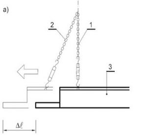
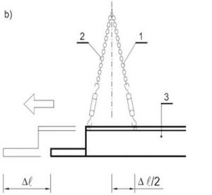
1. suspension before expansion, 2. suspension at maximum expansion, 3. radiant panel, Δl maximum expansion
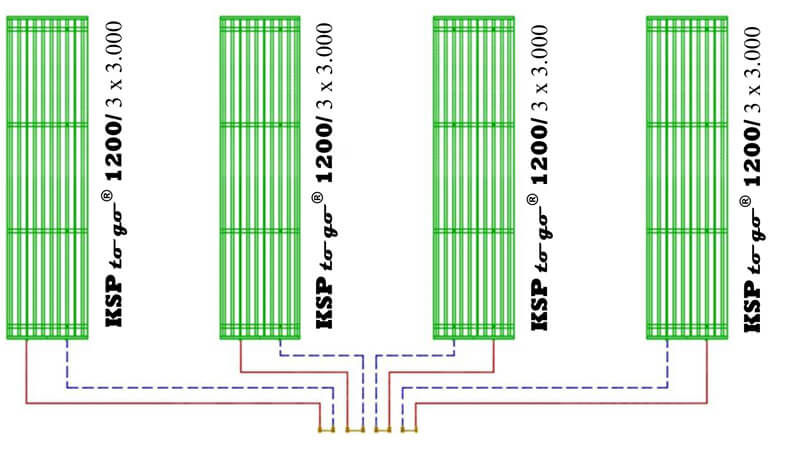
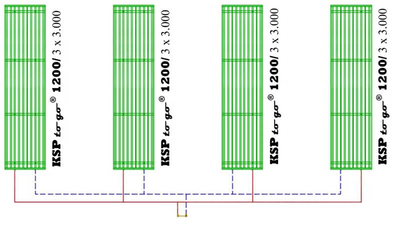
Connecting of radiant panel strips
1. Individual connection
2. Parallel connection
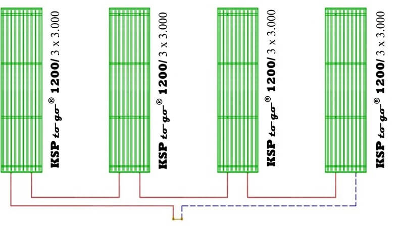
3. Serial connection
[1] Kabele, K., Hojer, O., Kotrbatý, M., Sommer, K., Petráš, D. Energy efficient heating and ventilation of large halls. Rehva guidebook no. 15. REHVA. Bruxelles 2011. ISBN 978-2-930521-06-0
The pressure losses in the KSP to go® range of goods can be divided as follows:
- Pressure losses of radiant panels Δp1
- Pressure losses of distributors Δp2
- Pressure losses of stainless steel corrugated hoses Δp3
The pressure losses of the radiant panels Δp1 can be found in Diagram 1. There you will find the data for each KSP to go® type depending on the flow rate. The values given are the pressure losses per meter and must always be multiplied by the total length of the heating tape.
The pressure losses of the KSP to go® distributor Δp2 can be found in the diagram 2. For clarity are the total values per strip already summed, so you can directly transfer the value in Pa or mbar. Alternatively, you can calculate the value yourself using the kvs values in the following table.
| Kvs [m3/h] | |
| Distributor kit KSP to go®600 (Box 4) | 7,40 |
| Distributor kit KSP to go®900 (Box 5) | 8,13 |
| Distributor kit KSP to go®1200 (Box 6) | 6,12 |
| 2 pcs KSP to go®-stainless steel corrugated hose | 5,94 |
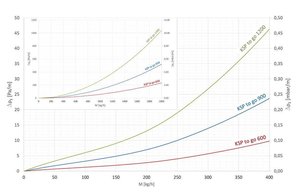
Diagram 1
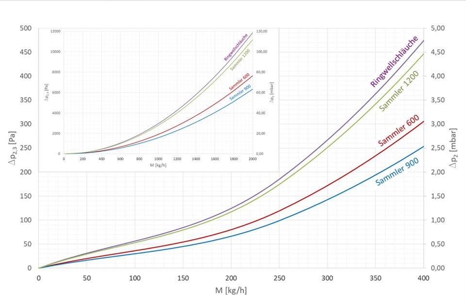
Diagram 2
If you plan radiant panels for the first time:
- Check the minimum flow rate if you connect all the heating strips in a room into a series (only one heating circuit). Check the pressure losses (in most systems, heating circuits can be arranged so, that the pressure losses are less than 50 kPa - 500 mbar, including pipes and valves)!
- If the pressure losses are larger, divide the strips into several heating circuits (but connect some strips parallel).
- Check the pressure losses in the pipes and make a hydraulic adjustment.
KSP to go® radiant panels are an extremely comfortable and energy-efficient heating system. They offer cozy warmth, freedom of drafts, dust and annoying noises. Admittedly, the initial investment is slightly higher than other heating systems. However, this pays for itself quickly through energy efficiency, maintenance-free operation and an extremely long service life. Hardly any product has such low lifecycle costs.
Let yourself be inspired.
Best regards from Herrieden, Germany
Yours radia.expert team
![]()
calculation example
You plan a room with the following dimensions: L x W x H = 6 x 4 x 3.5 m Heat losses: 1,700 W (ti = 18 ° C)
Condensing boiler: (tw1 =70 °C, tw2 = 55 °C)
Our online calculator calculates: 2strips, each 4 meters long, KSP to go®600
Result output::
| Box Nr. | Content | Piece | Qi,pc [W] | Qi,BAND [W] | Qi,TOT [W] |
| Box 1.2 | KSP to go®600 / 2 m | 4 | 554 | 1108 | 2216 |
| Box 4 | KSP to go®-Distributor kit 600 | 2 | 135 | 135 | 270 |
| Box 7 | KSP to go®-Connection kit 600 | 2 | 0 | 0 | 0 |
| Total: | 1.243 | 2.486 |
- Calculate the mass flow in a strip (parallel connection):

Determine the pressure losses of all your components on the basis of your results. - According to diagram 1, the pressure loss of the KSP to go® 600 panels is:
approx. 1 Pa/m (0,01 mbar/m).
Δp1 = R ∙ Li,Band = 1 Pa/m ∙ 4 m = 4 Pa (0,04 mbar) - According to diagram 2, the pressure loss of the KSP to go®600 distributor is: ΔP2 = approx. 30 Pa (0,30 mbar).
- According to diagram 2, the pressure loss of the KSP to go® corrugated hoses is:
Δp3 = ca. 45 Pa (0,45 mbar). - Add all pressure losses:
ΔpTOT = Δp1 + Δp2 + Δp3 = 4 + 30 + 45 = 79 Pa
As you can see, the pressure losses in this case are minimal. In general, these will be very low in most of the KSP to go® projects. This is why the control capability of the KSP to go® range is generally very high.
